

Thimbles and Roof Jacks
GT Exhaust Accessories
Installation and Operation Manual
NOTICE
This Exhaust Thimble Installation Guide must be expressly carried out in order to preserve WARRANTY COVERAGE. Ensure that all periodic checks and maintenance schedules are adhered to as directed.
IMPORTANT SAFETY WARNINGS
IF THERE IS ANY CONCERN ABOUT THE SAFETY OF THIS OR ANY SYSTEM, CLEAR THE AREA IMMEDIATELY OF ALL PERSONNEL AND CONTACT THE APPROPRIATE PERSON FOR FURTHER INSTRUCTIONS.
WARNING:ANYONE WORKING AROUND OR NEAR THE INSTALLATION SHOULD BE TRAINED IN THE PROPER SAFETY PRECAUTIONS AND PROCEDURES INCLUDING EMERGENCY SHUTDOWN. THESE PRECAUTIONS AND PROCEDURES MUST BE FOLLOWED.
WARNING: WORK ON THE INSTALLATION IS TO BE DONE ONLY BY TRAINED, QUALIFIED INDIVIDUALS. THIS INCLUDES ALL ELECTRICAL AND MECHANICAL WORK. ALL WORKERS MUST BE TRAINED IN THE PROPER SAFETY PRECAUTIONS AND PROPER ATTIRE MUST BE WORN AT ALL TIMES INCLUDING HARD HATS, SAFETY GLASSES, PROTECTIVE OUTERWEAR, EAR PROTECTION, AND STEEL-TOED BOOTS.
READ THROUGH THE ENTIRE MANUAL BEFORE PROCEEDING WITH ACTUAL INSTALLATION.
Introduction
Congratulations on your decision to partner with GT-Silex Exhaust through your recent purchase of GT-Silex Exhaust Accessories. Whether your purchase will be installed within an enclosure for backup power generation or in the harsh environments of off-shore, you can be sure that your purchase will manufactured to the highest quality and will perform as specified. This Exhaust Thimble Installation Guide will walk you through the necessary steps to successfully install and maintain your GT-Silex Exhaust product and will provide all other relevant information to ensure optimal effectiveness of your exhaust system’s operation.
Wall and Roof Thimble Overview
Thimbles provide transitions for exhaust piping where it is necessary to pass exhaust pipe through walls and roofs safely to the outside atmosphere. Thimbles are critical in complying with local fire and safety regulations by protecting wall and roof material from exhaust pipe heat.

Roof Jack Overview
Roof Jacks are designed for non-combustible metal enclosures only. They provide transitions for exhaust piping where it is necessary to pass exhaust pipe through walls and roofs safely to the outside atmosphere. Roof Jacks are critical in complying with local fire and safety regulations by protecting wall and roof material from exhaust pipe heat.
Receiving Inspection
Upon receipt of the system, check the nameplate against the packing list to verify the correct part numbers are received. Verify all items on the packing list are present.
Keep the shipping container to protect the unit until installation has been completed.
Prior to unpacking, check all components for shipping damage.
Advise gtexhaust.sales@nelsongp.com of shipping damage within three days of receipt of the product.
Storage
Leave any cardboard boxing, plywood covering, crating, and/or plastic covering intact until ready to install.
Be sure that all openings are closed so that no debris, vermin, rain, snow and/or ice can get into the unit.
Store the product on blocks, a minimum of 4” high, so that air can freely circulate around the unit.
Do not store the product in contact with the ground or in a wet, humid or flooded area.
Inspect the product’s body and mounting surfaces prior to installation. If there are any areas of significant damage, i.e. large dents, deep scratches, contact the factory before proceeding with installation.
Clean and remove any minor corrosion and refinish per GT Exhaust recommendations. If major corrosion has occurred such that the integrity of the unit is in question, contact GT Exhaust.
General Installation Considerations
Installation of GT Exhaust Accessories requires that the user ensure the entire exhaust system is properly designed before installing parts. Exhaust components such as expansion joints, rain caps, elbows, supports, etc. are critical installation pieces which, if they fail, may compromise the integrity of the system as well as damage other components and, possibly the engine and surrounding components.
The installation process of GT Exhaust Thimbles and Roof Jacks must be performed by trained and qualified personnel and approved by local building inspectors. Any procedures presented in this manual are suggestions and it is the responsibility of the Owner/Operator to arrange for these procedures to be performed by licensed contractors according to all applicable codes including local codes for your Municipality/City/County and State. These requirements are concerned with fire rated walls, a location that minimizes the possibility of damage to the Generator Set and interruption of the emergency system due to storms, foods, fire, vandalism, etc. In addition to these suggestions, before installing your GT Exhaust Accessories you should obtain the most up to date copies of the following documents from the National Electrical Code and other authorities:
National Electric Code, Articles 230, 250, 445, 517, 700.
National Fire Protection Association:
o No. 30 − Storage, Handling and Use of Flammable Liquids
o No. 37 − Stationary Combustion Engines and Gas Turbines
o No. 91 – Exhaust Systems for Air Conveying of Vapors, Gases, Mists, and Noncombustible Particulate Solids
o No. 99 − Essential Electrical Systems for Health Care Facilities
o No. 101 − Life Safety Code No. Systems
o No. 110 − Emergency and Standby Power Systems
NEMA MG1
Local Codes applicable to Generator Set or applicable installation. See your local building inspector.
Thimble Installation
For installation of Thimbles, the following procedure is recommended. Consult all applicable building, fire, and electrical codes. **
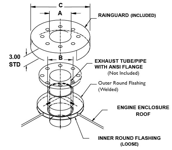
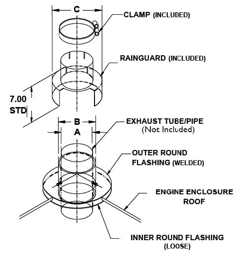
- Ensure all required components are present. Separate the upper portion of the thimble from the lower flashing and remove the Rain Guard. The exterior flashing is welded to the thimble body via triangular support gussets. Review Image 1 and 2 prior to installation.
- Locate an appropriate location where the exhaust piping will penetrate the roof or wall of the building. Ensure no structural members, electrical or plumbing, or other critical wiring/members are located at this location.
- Cut a hole in the roof/wall sized ¼” larger than the Thimble diameter or as the installing contractor sees fit.
- Apply a bead of Hi-Temperature Rated Sealant (Mil-A-46106B, 100 Series RTV) around the perimeter of the exterior flashing that will be in contact with the roof/wall and is a minimum of one inch from the edge of the flashing.
- Install the Thimble through the penetration so that the exterior flashing is flush to the roof/wall –clocking as needed.
- Apply a bead of Hi-Temperature Rated Sealant (Mil-A-46106B, 100 Series RTV) around the perimeter of the interior flashing that will be in contact with the roof/wall and is a minimum of one inch from the edge of the flashing.
- Install the interior flashing and clock as desired.
- Field install corrosion resistance fasteners into both the exterior and interior flashing surfaces, installing the fasteners wet with Hi-Temperature Rated Sealant (Mil-A-46106B, 100 Series RTV) in order to secure the Thimble.
- With Thimble Installed and fastened to Roof/Wall, insert exhaust piping through the ID Hole of the Thimble. Ensure that enough exhaust piping is installed to be able to install the rain cap and clamp. Note: Ensure that the exhaust piping is not in contact with the inner wall of the Thimble.
- Use Hi-Temperature Rated Sealant (Mil-A-46106B, 100 Series RTV) to install a ½” bead of sealant at the gap around the perimeter of the Thimble Body and the exterior flashing. Review Image 2.
- From the exterior of the building, install the Rain Guard over the Exhaust Pipe with the included Clamp.
- Tighten the Clamp in order to secure the Rain Guard to the Thimble.

Pre and Post Installation Checklist:
Prior to and subsequent to exhaust system installation, review the following check list to ensure that all components of your exhaust system are properly installed and ready for operation:
Ensure exhaust outlets are not located upwind or near any building air intakes.
Warning: Never allow the exhaust outlet to be positioned so that the exhaust gases are directed towards any openings or air entry routes (doors, windows, vents, etc…) of an occupied building. When discharging the hot exhaust gases out of the building do not direct them towards anything that could catch fire.
Ensure appropriate expansion joint is used at engine exhaust outlet and within the system to reduce premature failure due to thermal expansion.
Verify exhaust piping components are insulated as necessary to prevent operator burns and reduce pipe radiant heat losses.
Pipe sleeves or fire proof materials are used where exhaust pipe passes through building materials as per local and state codes.
Exhaust pipe includes rain cap or is horizontal.
- The purpose of the exhaust system is to safely discharge the engine combustion products into the atmosphere outside the building – ensure that local noise level ordinances are observed.
- Observe all OSHA mandated regulations for the safe rigging of exhaust equipment.
- Review Image 3 and 4 of Typical Exhaust System Installations
- Ensure that all mating surfaces are clean and free of foreign material before installation. When cleaning the surfaces, do not use abrasive materials such as steel wool or wire brushes. Use only isopropyl alcohol and clean, soft rags – Note:Do not use Chloride or Halide based cleaners


Maintenance
Note: Ensure exhaust components are cool prior to inspection and maintenance activities.
The recommended maintenance schedule for a typical exhaust system installation will consist of:
- Weekly: Physically examine exhaust system for any sign of gas leakage, cracks, or significant areas of damage.
- Quarterly: Examine the exhaust system for corrosion. Clean and remove any minor corrosion and refinish per GT Exhaust recommendations. If major corrosion has occurred such that the integrity of the exhaust system is in question, contact GT Exhaust for recommendation and resolution. Examine connecting flanges and support bolting – retighten any loose bolts as required.
**The installation information provided in this Exhaust Thimble Installation Guide should not be considered the advice of a properly licensed and qualified contractor, electrician, or building inspector or used in place of a detailed review of the applicable National Electric Codes, National Fire Protection Association, and other applicable local codes. Specific questions about how this information may affect any particular situation should be addressed to the local building inspector.
-Request Additional information on Exhaust Thimble Installation below-